
- info@trust-org.com
business-form domain was triggered too early. This is usually an indicator for some code in the plugin or theme running too early. Translations should be loaded at the init action or later. Please see Debugging in WordPress for more information. (This message was added in version 6.7.0.) in /home2/mfkdxpmx/public_html/wp-includes/functions.php on line 6131
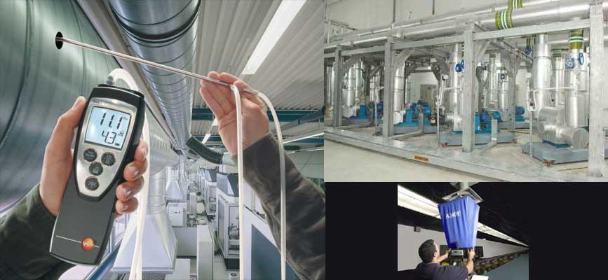
 Air pressure measurements for HVAC TAB procedures are accomplished with a manometer, connecting tubing and an appropriate sensing tip.
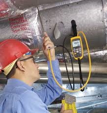
SP measurements are properly performed with a calibrated manometer and a Pitot tube or a static probe.
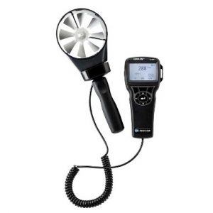
Air velocity measurements typically are performed in ducts; at the face of a Grille, Register or Diffuser (GRD) at coils, at filter banks or at other designated points.
These measurements are used to verify airflow performance of a particular piece of equipment or ducts under certain conditions.
The flow-measuring hood is a direct reading flow measurement device. It is designed with a fabric “sock” that covers the terminal air outlet device being measured. The conical or pyramid shaped hood collects all of the air entering or leaving an air outlet
and guides the airflow over the flow measuring instrumentation. Hoods generally are constructed so that the outlet tapers down to the metering section. A velocity measuring grid and calibrated differential pressure manometer in the hood will display the airflow in cfm (l/s) directly. However, it may be necessary to compare selected flow hood measurements
with Pitot tube traverses of ducts connected to a GRD to develop correction factors specific to a
system. This is up to the judgment of the CP.
The purpose of most rpm measurements in TAB work is to determine the rotational speed of a motor, fan or pump. The results are commonly expressed as rpm. This information is used to verify proper operational speed of the tested equipment.
Flow measurements in hydronic systems sometimes involve the use of externally installed (non-invasive) flow meter equipment.
Ultrasonic devices use sound waves and transit time technique to calculate direct flow readings.
The following applies to all hydronic systems:
a) The system shall be free of air and the instrument purged of air before use.
b) In Ultrasonic use, verify the appropriate transducers for the pipe size and location.
Ensure the instrument is appropriate for the system being tested and the type of measurements
being taken. Ensure the proper gel on the transducers is used at all times.
Ensure pipes are clean and free of insulation debris. Understand that erroneous readings may occur when measuring glycol solutions due to air entrainment in the solution.
c) Verify the instrument is appropriate for use on the system to be tested.